Are you ready to dive into the world of PC building and take control of your system’s nervous system? Connecting the various cables and wires from your case to the motherboard may seem like a daunting task, but fear not! In this ultimate guide, we’ll walk you through the process step by step, ensuring that you’ll have your new rig up and running in no time. By mastering the art of cable management and understanding the intricacies of front panel connectors, you’ll not only improve your system’s aesthetics but also optimize its performance and cooling. Let’s get started on this exciting journey!
The Importance of Proper Cable Management
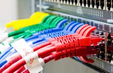
Before we delve into the specifics of connecting your front panel cables, let’s take a moment to appreciate the significance of cable management. A well-organized interior not only enhances the visual appeal of your build but also promotes better airflow, lower temperatures, and easier maintenance. Some key benefits of proper cable management include:
- Improved aesthetics: A clean and tidy case interior showcases your components and attention to detail.
- Better airflow: Neatly routed cables allow for unobstructed airflow, helping to keep your system cool.
- Easier upgrades and maintenance: With cables organized and out of the way, future upgrades and troubleshooting become more manageable.
Identifying Your Front Panel Connectors
Modern PC cases come equipped with a variety of front panel features, such as power and reset buttons, LED indicators, audio jacks, and USB ports. To utilize these functions, you’ll need to connect the corresponding cables to the appropriate headers on your motherboard. Here are the most common front panel connectors you’ll encounter:
- Power Switch: Connects to the “PWR_BTN” or “PWRSW” pins on the motherboard, allowing you to turn your system on and off.
- Reset Switch: Connects to the “RESET” pins, enabling you to restart your PC if needed.
- Power LED: Indicates the power status of your system and connects to the “PLED” or “PWR_LED” pins.
- HDD LED: Connects to the “HDD_LED” pins and flashes to indicate hard drive activity.
- Audio Connectors: Typically labeled “HD_AUDIO” or “F_AUDIO,” these connect to the front panel audio jacks.
- USB Connectors: USB 2.0 and USB 3.0 headers on the motherboard allow you to connect the front panel USB ports.
Step-by-Step Guide to Connecting Front Panel Cables
Now that you’re familiar with the various connectors, let’s walk through the process of connecting them to your motherboard:
Step 1: Consult Your Motherboard Manual
Before you begin, locate your motherboard manual and familiarize yourself with the layout of the front panel headers. Each motherboard manufacturer may have slightly different naming conventions or locations for these headers, so it’s crucial to refer to the manual for accurate information.
Step 2: Locate the Front Panel Cables
Inside your PC case, you’ll find a bundle of thin, multi-colored wires originating from the front panel. These cables are usually labeled or color-coded to help you identify their purpose. If the labels are unclear or absent, consult your case manual for guidance.
Step 3: Connect the Power Switch
Identify the power switch cable, which is typically labeled “PWR_SW” or “PWRBTN.” Carefully connect this cable to the corresponding pins on the motherboard, ensuring that the orientation is correct. The power switch cable is usually a two-pin connector, and the orientation does not matter.
Step 4: Connect the Reset Switch (Optional)
If your case has a reset switch, locate the cable labeled “RESET” and connect it to the appropriate pins on the motherboard. Like the power switch, the orientation of the reset switch cable does not matter.
Step 5: Connect the Power LED
Find the power LED cable, usually labeled “PLED” or “PWR_LED,” and connect it to the corresponding pins on the motherboard. Pay attention to the polarity of the LED connector, as incorrect installation may result in the LED not functioning. The positive (+) lead is typically indicated by a small triangle on the connector or a colored wire.
Step 6: Connect the HDD LED (Optional)
If your case has an HDD LED indicator, locate the cable and connect it to the “HDD_LED” pins on the motherboard. As with the power LED, ensure that the polarity is correct.
Step 7: Connect the Audio Connectors
Identify the front panel audio cable, usually labeled “HD_AUDIO” or “F_AUDIO,” and connect it to the corresponding header on the motherboard. This connector is typically larger than the others and can only be inserted in one orientation.
Step 8: Connect the USB Connectors
Locate the USB 2.0 and USB 3.0 cables from your case and connect them to the appropriate headers on the motherboard. USB 2.0 headers are usually labeled “USB” or “F_USB,” while USB 3.0 headers are labeled “USB3” or “F_USB3.” Ensure that the connectors are oriented correctly before applying gentle pressure to seat them properly.
Cable Management Tips and Tricks
With your front panel connectors now properly attached, it’s time to focus on overall cable management. Here are some tips and tricks to help you achieve a clean and organized build:
- Plan Your Cable Routes: Before connecting any cables, take a moment to plan out their paths. Consider the location of your components and the available cable management features in your case, such as grommets, tie-down points, and cable channels.
- Use Cable Ties and Velcro Straps: Utilize cable ties or Velcro straps to bundle cables together and secure them to the case. This helps keep cables tidy and prevents them from obstructing airflow.
- Route Cables Behind the Motherboard Tray: Whenever possible, route cables behind the motherboard tray to keep them out of sight. Many modern cases have ample space behind the tray for this purpose.
- Utilize Cable Management Accessories: Invest in cable management accessories like cable combs, extensions, and sleeved cables to further enhance the appearance of your build.
- Take Your Time: Don’t rush the cable management process. Take your time to carefully route and secure each cable, ensuring that they are neatly organized and not putting undue stress on any connectors.
Conclusion
By following this comprehensive guide, you should now have the knowledge and confidence to connect your system panel and case cables like a pro. Remember to consult your motherboard and case manuals for specific details, take your time, and prioritize proper cable management. With a little patience and attention to detail, you’ll be rewarded with a build that not only looks stunning but also performs at its best.
As technology continues to evolve, staying up-to-date with the latest cable management techniques and best practices is crucial. Keep an eye out for new products and trends that can further simplify and enhance the cable management process. Happy building, and may your system run cool, quiet, and powerful for years to come!


0