What you’ll need:
Unshielded twisted pair (UTP) patch cable
Modular connector (8P8C plug, aka RJ45)
Crimping tool
Cable tester (optional, but recommended)
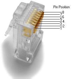
There are four pairs of wires in an Ethernet cable, and an Ethernet connector (8P8C) has eight pin slots. Each pin is identified by a number, starting from left to right, with the clip facing away from you.
The two standards for wiring Ethernet cables are T568A and T568B. T568B is the most common and is what we’ll be using for our straight Ethernet cable. The tables below show the proper orientation of the colored wires to the pins.
T568A Standard
Pin 1
White/Green
Pin 2
Green
Pin 3
White/Orange
Pin 4
Blue
Pin 5
White/Blue
Pin 6
Orange
Pin 7
White/Brown
Pin 8
Brown
T568B Standard
Pin 1
White/Orange
Pin 2
Orange
Pin 3
White/Green
Pin 4
Blue
Pin 5
White/Blue
Pin 6
Green
Pin 7
White/Brown
Pin 8
Brown
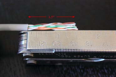
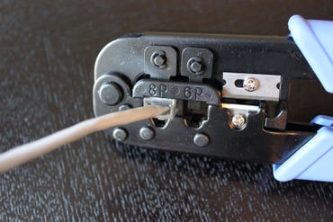
Step 1: Strip the cable jacket about 1.5 inch down from the end.
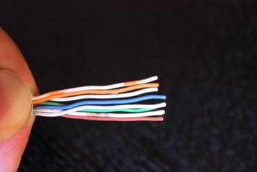
Step 2: Spread the four pairs of twisted wire apart. For Cat 5e, you can use the pull string to strip the jacket farther down if you need to, then cut the pull string. Cat 6 cables have a spine that will also need to be cut.
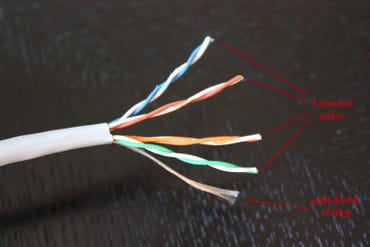
Step 3: Untwist the wire pairs and neatly align them in the T568B orientation. Be sure not to untwist them any farther down the cable than where the jacket begins; we want to leave as much of the cable twisted as possible.
Step 4: Cut the wires as straight as possible, about 0.5 inch above the end of the jacket.
Step 5: Carefully insert the wires all the way into the modular connector, making sure that each wire passes through the appropriate guides inside the connector.

Step 6: Push the connector inside the crimping tool and squeeze the crimper all the way down.
Step 7: Repeat steps 1-6 for the other end of the cable.
Step 8: To make sure you’ve successfully terminated each end of the cable, use a cable tester to test each pin.

When you’re all done, the connectors should look like this:

That’s it. For crossover cables, simply make one end of the cable a T568A and the other end a T568B. Now you can make Ethernet cables of any length, fix broken connectors, or make yourself a crossover cable. Happy crimping!