Signal deterioration in coaxial cable systems remains one of the most persistent challenges for network technicians and home users alike. Whether you’re experiencing pixelated television broadcasts, intermittent internet connectivity, or complete signal failures, understanding the physics behind signal attenuation and implementing proven remediation techniques can restore optimal performance. This comprehensive guide covers the technical causes of coaxial signal loss, diagnostic methodologies, and advanced solutions based on current industry standards.
Understanding Coaxial Signal Attenuation Fundamentals
Signal loss (attenuation) in coaxial systems occurs through specific physical mechanisms that affect transmission quality. According to the latest research, coaxial signal deterioration primarily happens through two main physical processes:
Skin Effect Loss
Skin effect loss occurs when high-frequency signals flow primarily along the outer surface of the inner conductor rather than utilizing its entire cross-section. This phenomenon increases with frequency and reduces the effective conductor area, converting signal energy into heat and causing progressive attenuation. Modern RG6 cables experience approximately 5.6dB/100ft loss at 1GHz due to skin effect, while higher-quality RG11 cables reduce this to approximately 3.5dB/100ft at the same frequency.
Dielectric Loss
The second major attenuation mechanism, dielectric loss, occurs when the insulating material between conductors absorbs energy from the electromagnetic field. This loss increases linearly with frequency and disproportionately affects higher-frequency signals, making it particularly relevant for modern high-definition digital transmissions. Materials like foam polyethylene (used in premium cables) offer lower dielectric loss compared to solid polyethylene dielectrics.
Primary Causes of Signal Degradation
According to the latest TIA-568.4-D standard (updated in 2023), several factors can contribute to coaxial signal loss beyond the inherent physical limitations:
Physical Cable Damage
Physical damage to coaxial cables represents one of the most common causes of signal problems:
- Excessive Bending: Exceeding the minimum bend radius (typically 4.5 inches for RG6) can permanently damage internal geometry
- Kinking or Crushing: Damage to the cable’s structure alters impedance at the affected point, creating signal reflections
- Jacket Compromise: Cuts or tears in the outer jacket allow moisture ingress, which progressively degrades performance
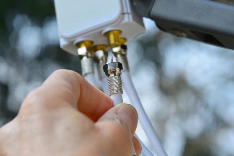
Connection Issues
Approximately 60% of all coaxial signal problems originate at connection points:
- Loose Connectors: Hand-tight connections often loosen over time, creating intermittent connectivity
- Corrosion: Especially in outdoor installations, connector corrosion creates high-resistance connections
- Improper Termination: Poor crimping technique or using the wrong connector type for the cable creates impedance mismatches
Environmental Factors
Environmental conditions significantly impact coaxial performance over time:
- Moisture Exposure: Water infiltration dramatically increases dielectric losses
- Temperature Fluctuations: Cause expansion and contraction that can loosen connections
- UV Radiation: Degrades cable jacketing, eventually compromising the cable structure
Scientific Measurement of Signal Loss
Required Testing Equipment
According to industry standards, proper diagnosis requires appropriate testing tools:
- Signal Level Meter: Measures actual signal strength in dBmV
- Cable Analyzer: Tests for multiple parameters including insertion loss and return loss
- Time Domain Reflectometer (TDR): Locates specific points of impedance change within the cable
- Spectrum Analyzer: Identifies frequency-specific issues and interference
Understanding Signal Specifications
| Signal Type | Optimal Signal Level | Minimum Acceptable | Maximum Acceptable |
|---|---|---|---|
| Digital Cable TV | -5 dBmV | -15 dBmV | +15 dBmV |
| QAM Internet | 0 dBmV | -10 dBmV | +10 dBmV |
| Satellite (L-band) | -25 dBm | -65 dBm | -15 dBm |
| DOCSIS 3.1 | 0 dBmV | -7 dBmV | +7 dBmV |
Signal levels outside these ranges will cause intermittent or complete service failure
Systematic Troubleshooting Protocol
1. Visual Inspection Methodology
Begin with a comprehensive visual assessment following these technical procedures:
- Trace the entire cable path from source to termination point
- Identify any visible damage, improper bends, or environmental exposure
- Verify proper support and strain relief at all mounting points
- Document any questionable sections for further testing or replacement
2. Connection Integrity Verification
Connection issues represent the most common point of failure:
- Using an 8-inch adjustable wrench, verify all F-connectors are properly torqued to 30 in-lb (±10%) as specified in TIA-568.4-D
- Inspect connectors for signs of corrosion, water ingress, or improper seating
- Verify center conductor protrusion is within 1/16″ to 3/16″ specification
- Confirm all compression connectors are fully compressed with no visible gaps
3. Signal Path Analysis
For complex systems or persistent issues, a systematic signal path analysis is essential:
- Begin testing at the signal source (demarc, antenna, etc.) and measure signal levels
- Proceed methodically through the system, testing after each component (splitter, amplifier, etc.)
- Calculate actual loss per 100 feet and compare to manufacturer specifications
- Document deviation from expected parameters to identify problematic segments
Advanced Signal Remediation Techniques
Strategic Amplification Implementation
When cable runs exceed length limits or multiple splits reduce signal strength, proper amplification becomes necessary:
- Pre-Amplifiers: Install within 10 feet of the signal source before any splitters
- Typically provide 15-25 dB gain with minimal noise introduction
- Select models with return path capabilities for bidirectional services
- Distribution Amplifiers: Implement after initial splitting to compensate for distribution losses
- Choose unity gain models for maintaining consistent levels
- Install in environmentally protected locations for maximum reliability
- Line Extenders: Use for exceptionally long cable runs exceeding 150 feet
- Select models with appropriate frequency range (5-1220 MHz for full DOCSIS 3.1 compatibility)
- Include proper grounding per NEC Article 830
Connection Quality Optimization
Based on the 2025 updated TIA specifications, the following connector improvements provide substantial benefits:
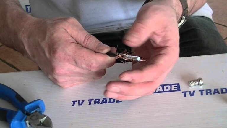
- Compression Connector Upgrade:
- Replace crimp or twist-on connectors with compression-style
- Ensure proper compression tool calibration (typically 12-15 psi for RG6)
- Use weather-sealed connectors for all outdoor applications
- Specialized Connection Environments:
- For high-vibration areas: Use connectors with integrated locking mechanisms
- For high-moisture locations: Apply dielectric grease before connection
- For corrosive environments: Select connectors with corrosion-resistant platings (typically nickel or gold)
Cable Replacement Specifications
When cable replacement becomes necessary, selecting the appropriate cable type is crucial:
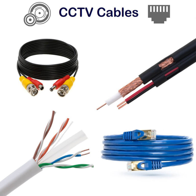
| Cable Type | Ideal Use Case | Max Distance | Signal Loss (dB/100ft @ 1GHz) |
|---|---|---|---|
| RG59 | Legacy/CCTV applications | 150 ft | 6.8 dB |
| RG6 | Standard residential | 200 ft | 4.2 dB |
| RG6 Quad Shield | High-interference areas | 200 ft | 4.0 dB |
| RG11 | Long runs/commercial | 400 ft | 2.7 dB |
Source: ANSI/TIA-568.4-D Broadband Coaxial Cabling and Components Standard (2023 Edition)
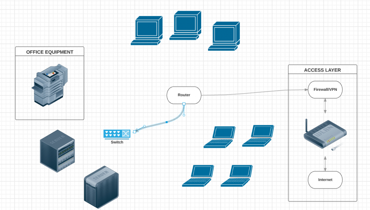
Advanced System Design Considerations
Optimal Splitter Placement
The location and quality of splitters significantly impact system performance:
- Implement the “home-run” design where possible, with centralized splitting
- Use splitters with appropriate bandwidth (5-2300 MHz for DOCSIS 3.1 compatibility)
- Select splitters with minimal through-loss on primary ports (3.5dB or less)
- Install terminators on all unused ports to prevent signal reflection
Interference Mitigation Strategies
For installations in high-interference environments:
- Physical Separation: Maintain minimum 6-inch spacing from AC power lines
- Enhanced Shielding: Upgrade to quad-shield cables in problematic areas
- Ferrite Installation: Add clip-on ferrites at strategic points to filter common-mode interference
- Proper Grounding: Implement multi-point grounding system per NEC Article 830.100
Preventative Maintenance Protocol
Regular System Evaluation
Implementing a structured maintenance program prevents gradual performance deterioration:
- Quarterly Inspection Schedule:
- Visually inspect all accessible connections
- Verify connection tightness at termination points
- Check for new sources of potential interference
- Document any changes to the system configuration
- Annual Performance Testing:
- Conduct comprehensive signal level measurements
- Perform sweep testing across the entire frequency range
- Verify return path performance for interactive services
- Update system documentation with current measurements
Environmental Protection Enhancements
To extend system lifespan in challenging environments:
- Outdoor Connection Protection:
- Apply self-amalgamating tape to all outdoor connections
- Implement drip loops to prevent water tracking along cables
- Install proper cable entry points with weatherproof boots
- Conduit and Pathway Management:
- Use appropriate conduit for underground or exposed runs
- Implement proper bend radius protection at direction changes
- Seal all building penetrations with appropriate materials
Conclusion
Coaxial cable signal loss represents a multifaceted technical challenge requiring systematic diagnosis and targeted remediation. By understanding the underlying physical principles of signal attenuation, implementing proper measurement techniques, and applying industry-standard solutions, most coaxial signal issues can be effectively resolved.
The transition to higher-frequency applications (including DOCSIS 3.1 and 4.0) makes proper installation, maintenance, and troubleshooting increasingly critical. Regular system evaluation, strategic component selection, and adherence to current technical standards ensure optimal performance and reliability in modern coaxial systems.
For persistent or complex issues, professional assessment with calibrated test equipment may be necessary. However, by following the systematic approach outlined in this guide, technicians and informed users can diagnose and resolve the vast majority of coaxial signal problems, restoring optimal performance for critical communications services.