Electromagnetic interference (EMI) poses a persistent challenge to signal integrity in coaxial cable networks. As data rates increase and signal sensitivity grows with advancing technology, even minor interference can significantly impact network performance, causing packet loss, increased jitter, and reduced throughput. This comprehensive technical guide examines the latest standards-compliant methods for identifying, preventing, and eliminating interference in coaxial networks based on the most current industry research and specifications.
Understanding Electromagnetic Interference in Coaxial Systems
Coaxial cables consist of a center conductor, dielectric insulator, conductive shield, and outer jacket-a design specifically engineered to contain signals within the cable while rejecting external interference. Despite this inherent protection, interference can still penetrate or originate within these systems through various mechanisms.
Primary Sources of Signal Interference
Signal degradation in coaxial networks stems from multiple sources that network engineers must identify and address:
- Electromagnetic Interference (EMI): External electromagnetic fields from electrical equipment including:
- Variable frequency drives
- Motors and generators
- Switching power supplies
- Power lines carrying 50/60Hz signals
- Radio Frequency Interference (RFI): A subset of EMI specific to radio frequencies from:
- Nearby radio transmitters
- Wireless communication devices
- Microwave equipment
- Intentional RF emitters
- Internal Cable Interference:
- Crosstalk: Signal leakage between adjacent cables
- Impedance mismatches: Causing signal reflections at connection points
- Ground loops: Unwanted current in the shield causing visible or audible interference
Measuring Interference Impact
The impact of interference can be quantified through several technical measurements:
- Signal-to-Noise Ratio (SNR): Measures the ratio of desired signal to unwanted noise
- Bit Error Rate (BER): Percentage of bits received with errors due to interference
- Return Loss: Measures signal reflections caused by impedance mismatches
- Insertion Loss: Signal power loss through the cable length, affected by interference
Recent testing protocols outlined in IEC 61196-1-112:2025 have established improved methodologies for measuring return loss and VSWR (Voltage Standing Wave Ratio), particularly crucial for applications above 1.8 GHz where interference sensitivity increases significantly.
Shield Construction and Effectiveness
The shield is the primary defense mechanism against EMI/RFI interference in coaxial systems. Understanding shield construction types and their relative effectiveness is essential for selecting appropriate cables for specific environments.
Shield Types and Construction
Modern coaxial cables employ several shielding approaches, each with distinct advantages:
| Shield Type | Construction | Coverage | Best for | EMI Protection |
|---|---|---|---|---|
| Standard (Single) | Aluminum foil + aluminum braid | 60-95% | Residential | Good |
| Tri-Shield | Foil + braid + second foil | 98-99% | Commercial | Very Good |
| Quad-Shield | Foil + braid + foil + braid | >99% | Industrial | Excellent |
Quad-shield coaxial cables provide superior interference rejection through four alternating layers (foil-braid-foil-braid), making them particularly effective in high-interference environments where signal integrity is paramount.
Shield Effectiveness Factors
Shield performance is influenced by several technical factors beyond just the number of layers:
- Coverage percentage: Higher coverage results in better EMI rejection
- Shield material conductivity: Copper shields offer approximately 40% better conductivity than aluminum
- Shield thickness: Thicker shields provide better low-frequency protection
- Shield continuity: Any gaps in shielding create vulnerability points for interference entry
- Transfer impedance: Lower transfer impedance indicates better shielding effectiveness
Shield effectiveness is measured in decibels (dB), with higher values indicating better protection. Professional-grade quad-shield cables typically offer 90dB or higher EMI rejection across their operational frequency range.
For environments requiring maximum protection, consider cables meeting MIL-DTL-17 specifications, which provide superior EMI performance validated through rigorous military-standard testing protocols.
Installation Best Practices for Interference Prevention
Proper installation techniques significantly impact a coaxial network’s susceptibility to interference. Following industry-endorsed best practices ensures optimal performance even in challenging environments.
Cable Routing and Separation Guidelines
The physical placement of coaxial cables relative to potential interference sources is critical:
- Maintain minimum 30cm separation from 480VAC power lines (per NEC 300.3(C)(1))
- Cross power lines at 90-degree angles when unavoidable
- Route cables away from EMI sources including motors, fluorescent lighting, and power distribution panels
- Avoid creating loops in coaxial cabling, as these can act as antennas for picking up interference
- Use dedicated cable pathways, trays, or conduits for coaxial runs
Proper Grounding Techniques
Effective grounding represents one of the most critical aspects of interference prevention:
- Connect shields to a low-impedance ground point (<5Ω per ANSI/TIA-607-B)
- For high-frequency applications above 10MHz, implement multi-point grounding
- For low-frequency applications below 1MHz, use single-point grounding
- Avoid ground loops by implementing star grounding topologies
- Use exothermic welding or compression fittings for ground connections
- Ensure compliance with NEC Article 810/820 requirements for antenna and CATV grounding
When testing ground resistance, use a dedicated ground resistance tester rather than a standard multimeter for accurate measurements. The ideal ground resistance should be under 5 ohms for optimal shield performance.
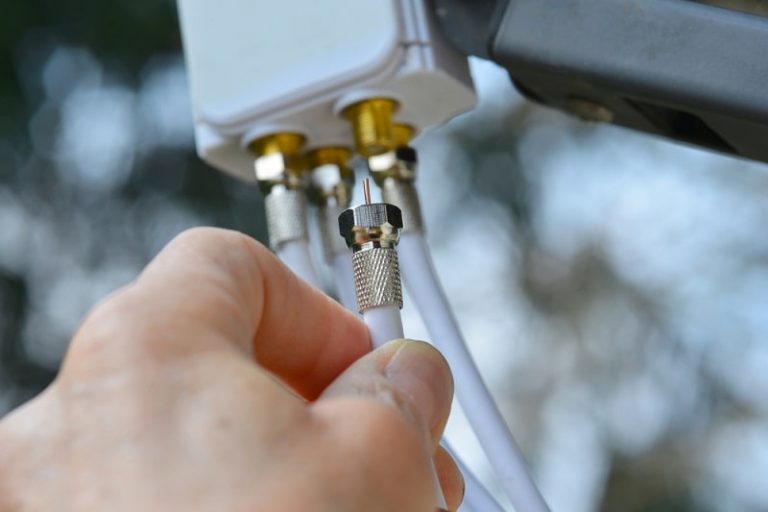
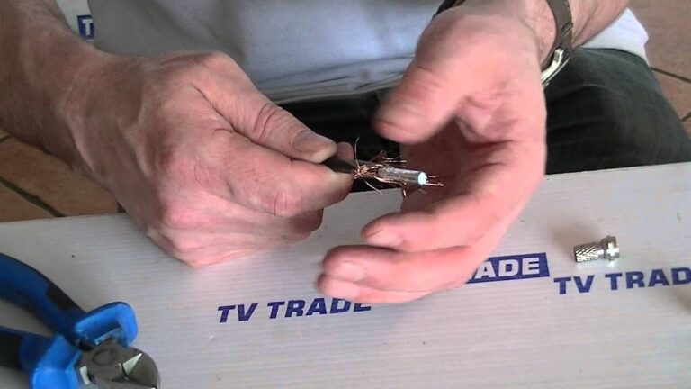
Connector Selection and Installation
Proper connector selection and installation are essential for maintaining shield continuity and impedance matching:
- Select connectors with return loss ratings of <-55dB (per IEC 61169-24)
- Use compression connectors rather than twist-on types for better shield contact
- Ensure connectors maintain proper impedance matching (typically 75Ω for video applications)
- Verify that connector installation doesn’t compromise the cable shield
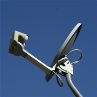
- Use weatherproof connectors with appropriate O-rings for outdoor installations
For detailed instructions on proper coaxial connector installation, see our guide to terminating coaxial cables.
Advanced Interference Mitigation Solutions
When standard installation practices prove insufficient, advanced mitigation techniques can provide additional protection against persistent interference.
Ferrite Components
Ferrite cores or chokes function as passive filters to remove high-frequency interference:
- Installation method: Attach ferrite cores around coaxial cables near their connectors
- Effective frequency range: Typically 25MHz to 1GHz
- Selection criteria: Core composition and dimensions must match the interference frequency
- Performance impact: Can provide 10-25dB additional noise suppression
Ferrite components work by introducing impedance to common-mode currents at problematic frequencies while allowing the desired differential signals to pass through unaffected.
Signal Filtering and Conditioning
Signal filtering technologies selectively remove interference at specific frequencies:
- Low-pass filters: Block high-frequency noise above the desired signal frequency
- High-pass filters: Remove low-frequency interference below the signal frequency
- Band-pass filters: Allow only a specific frequency range to pass
- π-type filters: Effective for handling specific frequency interference when properly tuned
For cable television and broadband applications, installing a π-type filter with a cutoff frequency (fc) of 30MHz and Q factor of 0.707 can effectively suppress power line interference while preserving desired signals.
Strategic Amplifier Placement
Properly located signal amplifiers can boost desired signals above the interference noise floor:
- Install amplifiers as close as possible to signal sources
- Use high-linearity amplifiers with low noise figures
- Properly terminate all unused ports to prevent reflection-based interference
- Consider bi-directional amplifiers in two-way systems to maintain signal integrity
Testing and Troubleshooting Interference Issues
Systematic testing is essential for identifying and resolving interference issues in coaxial networks.
Signal Measurement Equipment
Professional testing requires appropriate equipment:
- Time Domain Reflectometer (TDR): Identifies impedance mismatches, shield breaks, and fault locations
- Spectrum Analyzer: Visualizes frequency-specific interference patterns
- Signal Level Meter: Measures signal strength across relevant frequency bands
- Cable Certifier: Validates cable performance against industry standards
The Fluke Networks DSX-CHA003 Coax Adapter paired with the DSX CableAnalyzer™ Series provides comprehensive coaxial testing to TIA insertion loss limits over the full frequency range (5 to 1002 MHz).
Diagnosing Interference Patterns
Different interference sources produce recognizable patterns that help identify their origin:
- 60Hz hum or bands: Power line interference
- Horizontal bars or rolling interference: Ground loop issues
- Speckling or snow: High-frequency noise (often from digital equipment)
- Cross-channel interference: Indicates shield effectiveness problems
For a detailed guide to testing coaxial cable signal quality, visit our cable signal testing guide.
Systematic Troubleshooting Approach
Follow this structured methodology to diagnose and resolve interference issues:
- Document symptoms precisely (intermittent/constant, affecting specific frequencies, etc.)
- Isolate the problem by disconnecting and testing segments individually
- Check physical installation for routing problems, damaged cables, or improper grounding
- Verify connector integrity including shield termination and impedance matching
- Test with alternative equipment to identify device-specific issues
- Implement mitigation techniques based on interference type and source
- Document solutions for future reference and maintenance
Industry Standards and Compliance
Adherence to established technical standards ensures both effectiveness and safety in coaxial installations.
ANSI/TIA-568-4.D Requirements
The ANSI/TIA-568-4.D specification establishes critical parameters for 75-ohm broadband coaxial cabling:
- Cabling Subsystem 1 (outlet to first distribution point):
- 46 meters maximum length for RG6
- 90 meters maximum length for RG11
- Cabling Subsystem 2 (between distribution points):
- 46 meters maximum for RG6
- 100 meters maximum for RG11
These length limitations help minimize interference vulnerabilities by reducing signal attenuation and exposure to external EMI sources.
NEC Code Compliance
The National Electric Code (NEC) establishes safety requirements that also impact interference performance:
- NEC requires proper grounding of coaxial cable shields
- Only stranded or solid copper conductors are permitted (CCA is non-compliant)
- Cable installations must maintain minimum separation from power conductors
- Proper fire ratings are required for cables installed in plenum or riser spaces
Non-compliance with NEC requirements can result in both safety hazards and increased interference susceptibility.
UL/ETL Certification
UL (Underwriters Laboratories) and ETL (Electrical Testing Laboratories) certifications verify that cables meet established safety and performance standards:
- Verify cables carry appropriate UL/ETL marks
- Ensure certification matches intended installation environment
- Check that cables meet designated Category ratings
- Confirm flame resistance ratings appropriate to installation location
Practical Implementation: Case Studies
Examining real-world interference scenarios provides valuable insights into effective mitigation strategies.
Residential Environment: Cable Modem Performance
Problem: A residential cable modem exhibited 40% uncorrected errors and frequent disconnections despite having adequate signal strength.
Solution: Moving the cable modem approximately three feet away from a power distribution panel eliminated virtually all errors. The electromagnetic field from the panel was inducing interference in the coaxial cable connecting to the modem. This simple relocation resolved the issue without requiring cable replacement or additional equipment.
Key learning: Physical separation from interference sources can be a simple yet highly effective solution.
Commercial Application: Security Camera Network
Problem: A retail establishment’s coaxial-based CCTV system displayed horizontal banding and intermittent video loss during peak business hours.
Solution: Analysis revealed multiple issues requiring a comprehensive approach:
- Replaced standard RG6 with quad-shield RG6 cables
- Installed ferrite cores at both ends of each cable
- Implemented proper single-point grounding
- Relocated cables away from fluorescent lighting ballasts
This combination eliminated the interference issues completely, resulting in clear video quality regardless of store activity levels.
Industrial Environment: Process Control Monitoring
Problem: An industrial facility’s monitoring system using coaxial cables experienced intermittent data corruption when nearby machinery activated.
Solution:
- Upgraded to RG11 quad-shielded cables with 90dB EMI rejection
- Implemented proper conduit separation from power cables
- Installed inline filters tuned to the specific interference frequencies
- Added proper surge protection at both ends of the cable
The combination of these techniques provided a robust solution that maintained data integrity even during peak machinery operation.
Conclusion: Implementing a Comprehensive Interference Management Strategy
Effectively preventing and eliminating interference in coaxial networks requires a multi-faceted approach:
- Select appropriate cable types with shielding matched to the electromagnetic environment
- Implement best practices for installation with emphasis on proper routing, grounding, and connector termination
- Use advanced mitigation techniques when necessary, including ferrites, filters, and strategic amplification
- Test thoroughly using appropriate equipment and methodologies
- Comply with standards to ensure both performance and safety
- Document solutions to build institutional knowledge for maintenance and future installations
Following these guidelines will result in coaxial networks that deliver optimal performance even in challenging electromagnetic environments. For additional information on related topics, visit our guides on coaxial cable basics, surge protection, and troubleshooting cable failures.Preventing & Eliminating Coaxial Cable Interference: 2025 Guide