In today’s high-speed digital infrastructure, coaxial cable remains a vital component for transmitting signals across various applications. Whether you’re installing a home network, setting up a CCTV system, or establishing a satellite connection, understanding the maximum coaxial cable length limitations is crucial for maintaining signal integrity and ensuring optimal performance.
Signal degradation over distance represents one of the most significant challenges when working with coaxial cable installations. This comprehensive guide examines the technical factors that determine maximum cable lengths, explains industry standards, and provides proven solutions for overcoming these limitations in professional applications.
Technical Factors Determining Maximum Cable Length
Several fundamental electrical and physical characteristics influence how far a signal can travel through coaxial cable before degradation becomes problematic.
Signal Attenuation: The Primary Limiting Factor
Signal attenuation – the gradual loss of signal strength over distance – represents the most significant constraint on maximum coaxial cable length. This phenomenon occurs as electromagnetic energy dissipates while traveling through the cable’s conductor and dielectric materials.
Attenuation is measured in decibels (dB) per unit length (typically per 100 feet or 100 meters) and increases with frequency. This explains why higher frequency applications like satellite TV or 5G installations require shorter cable runs than lower frequency systems.
The following table illustrates typical attenuation values for common coaxial cable types at various frequencies:
| Cable Type | 400 MHz | 900 MHz | 1800 MHz | 2600 MHz |
|---|---|---|---|---|
| RG-6 | 3.4 dB | 5.2 dB | 6.5 dB | 7.5 dB |
| RG-11 | 2.1 dB | 3.0 dB | 4.5 dB | 5.8 dB |
| LMR-400 | 1.5 dB | 2.1 dB | 2.8 dB | 3.3 dB |
Values represent attenuation per 100 feet (30.5 meters)
Factors Contributing to Signal Loss
Beyond basic attenuation, several additional factors influence signal integrity over distance:
- Skin Effect – At higher frequencies, electrical current flows primarily along the conductor’s outer surface rather than throughout the entire cross-section, effectively increasing resistance
- Dielectric Loss – Energy dissipation through the insulating material between conductors, which increases proportionally with frequency
- Impedance Variations – Inconsistencies in the cable’s characteristic impedance (typically 75Ω for video applications or 50Ω for RF systems) create signal reflections
- Connector Quality – Each connection point introduces additional signal loss and potential impedance mismatches
For a deeper analysis of coaxial cable impedance characteristics, refer to our guide on mastering coaxial cable impedance for optimal system performance.
Maximum Cable Lengths by Cable Type and Application
Different applications tolerate varying degrees of signal loss, and cable specifications influence maximum effective distances considerably.
Residential Cable TV and Internet Applications
For standard residential installations:
- RG-6: The industry standard for cable TV and internet service typically supports runs up to 150 feet without amplification
- RG-11: With lower attenuation characteristics, these heavier cables can extend reliable signals to approximately 300 feet
- Quad-Shield RG-6: Offers similar distance capabilities to standard RG-6 but with superior noise immunity in electrically congested environments
Learn more about the benefits of enhanced shielding in our article on quad-shield coaxial cable advantages.
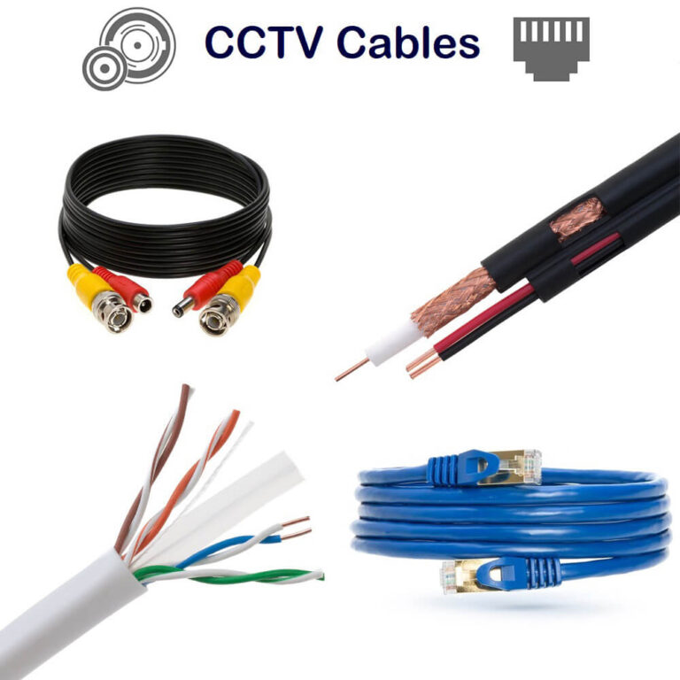
CCTV and Security Applications
Video surveillance systems have specific requirements:
- RG-59: Suitable for analog CCTV applications up to approximately 750 feet
- RG-6: Recommended for HD security cameras with distances up to 500 feet
- RG-11: Capable of supporting extended camera placements up to 1000+ feet
For comprehensive installation guidance for security applications, see our CCTV cable distance guide.
Satellite Systems and High-Frequency Applications
High-frequency satellite communications require special considerations:
- Satellite TV (Ku/Ka band): Maximum recommended length for RG-6 is typically 100-150 feet
- GNSS/GPS Antenna Feeds: Generally limited to 50-95 meters depending on specific system requirements
- Wireless Transmission Lines: For 2.4GHz applications, premium cables like LMR-400 should be limited to approximately 60 feet
Industry Standards and Maximum Length Specifications
Professional installations should adhere to established industry standards that define maximum supportable distances.
ANSI/TIA-568 Requirements
The ANSI/TIA-568 standard (2023 revision) provides authoritative guidelines for commercial telecommunications cabling. For 75-ohm broadband coaxial cabling, TIA-568-C.4 specifies:
- Cabling Subsystem 1 (outlet to first distribution point):
- RG-6: 46 meters (150.9 feet) maximum
- RG-11: 90 meters (295.3 feet) maximum
- Cabling Subsystem 2 (between distribution points):
- RG-6: 46 meters (150.9 feet) maximum
- RG-11: 100 meters (328.1 feet) maximum
These specifications apply to frequencies ranging from 5 to 1002 MHz, covering most standard broadband applications.
Satellite Service Provider Requirements
Satellite internet providers often specify maximum cable lengths to ensure reliable service. For example, Viasat installations require:
- High-speed (3.0 GHz), RG-6, 75-ohm, solid copper coaxial cable
- Maximum length of 150 feet
- Compression F-type connectors with weather sealing
- Minimum bend radius of 6 inches
These specifications prevent voltage drop between the satellite modem and outdoor unit from exceeding critical thresholds.
Strategies for Overcoming Length Limitations
When installations require distances exceeding standard recommendations, several technical approaches can extend the effective range.
Strategic Placement of Amplifiers
Amplifiers can compensate for signal loss over distance:
- Preamplifiers: Place as close to the signal source as possible
- Line Amplifiers: Install at strategic intervals to restore signal levels
- Distribution Amplifiers: Use when splitting signals to multiple destinations
When selecting amplifiers, consider:
- Noise Figure: Lower values (< 3dB) minimize additional noise introduction
- Gain: Match to compensate for specific cable loss
- Frequency Range: Must support all channels/frequencies in use
Cable Selection Optimization
Choosing the appropriate cable type represents the most fundamental strategy for maximizing distance:
- For critical long-distance applications, upgrading from RG-6 to RG-11 can nearly double the maximum effective distance
- Consider specialized low-loss variants like LMR-400 or RF-9913 for applications requiring superior performance
- Verify cable quality through manufacturer specifications rather than relying solely on RG designation
Our detailed comparison of RG-11 coaxial cable characteristics provides additional guidance on when to select this premium option.
Installation Best Practices to Maximize Performance
Proper installation techniques can dramatically extend the effective range of coaxial installations:
- Maintain appropriate bend radius (typically 6-10× the cable diameter) to prevent internal damage
- Minimize connectors and splices, as each introduces additional signal loss
- Use high-quality compression connectors rather than crimp-on varieties
- Implement proper grounding and bonding to minimize interference
- Shield cables from potential EMI sources like power lines or motors
Learn more about proper termination techniques in our guide to terminating coaxial cable.
Alternative Technologies for Extreme Distances
For installations requiring distances beyond what coaxial cable can reliably support:
- Fiber Optic Conversion: Convert signals to optical for transmission over multi-kilometer distances
- Point-to-Point Wireless: Utilize directional antennas for line-of-sight connections
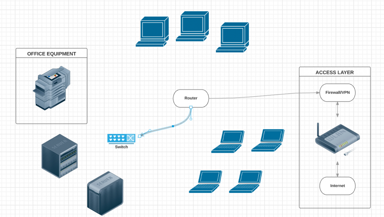
- Network-Based Distribution: Convert signals to IP packets for transmission over structured cabling or networks
Troubleshooting Length-Related Signal Issues
Identifying when cable length is the root cause of signal problems requires systematic troubleshooting.
Common Symptoms of Excessive Length
Signal issues arising from excessive cable length typically manifest as:
- Intermittent connectivity or sporadic signal dropouts
- Pixelation or artifacts in video applications
- Reduced bandwidth or data speeds
- Increased noise or interference patterns
- Complete signal loss at higher frequencies while lower frequencies remain functional
Diagnostic Approach
When troubleshooting potential length-related issues:
- Visual Inspection: Check for physical damage, excessive bends, or crushed sections
- Connectivity Test: Verify all connections are properly seated and secured
- Isolation Testing: Replace with a shorter temporary cable to isolate length as the variable
- Signal Measurement: Use a signal meter to measure levels at both source and destination
- TDR Testing: For advanced diagnostics, utilize Time Domain Reflectometry to locate impedance mismatches
For a complete walkthrough of diagnostic techniques, read our cable signal testing guide.
Cost-Benefit Analysis: Balancing Performance with Budget
When addressing distance limitations, multiple approaches offer different cost-efficiency profiles:
Cable Upgrade vs. Amplification
| Solution | Advantages | Disadvantages | Approximate Cost Impact |
|---|---|---|---|
| Premium Cable (RG-11) | No active components to fail, one-time cost | Higher material cost, more difficult to install | +40-60% over standard cable |
| Signal Amplification | Uses standard cable, potentially lower initial cost | Requires power, introduces potential points of failure | +15-30% plus ongoing power costs |
| Fiber Conversion | Virtually unlimited distance, complete EMI immunity | Significantly higher component costs, specialized installation | +100-200% over coaxial solutions |
Implementation Example: Extending a 400-foot Run
For a CATV installation requiring a 400-foot run from the demarcation point to the viewing location:
Option 1: Premium Cable Only
- Use RG-11 for the entire run
- Install a passive return path filter at the TV location
- Total signal loss: approximately 8.4dB at 1GHz
Option 2: Standard Cable with Amplification
- Use RG-6 with a +15dB distribution amplifier at the 150-foot mark
- Install a second +7dB amplifier at the 300-foot mark
- Total signal budget: +22dB gain, approximately 18dB loss, resulting in +4dB net gain
Option 3: Hybrid Approach
- Use RG-11 for the main 300-foot run
- Install a +10dB amplifier at the 300-foot mark
- Use standard RG-6 for the final 100 feet
- Total signal budget: +10dB gain, approximately 10dB loss, resulting in neutral net impact
Future Trends in Coaxial Cable Technology (2025)
Recent innovations are expanding the capabilities of coaxial infrastructure:
- Advanced Dielectric Materials: New foam polyethylene formulations provide 15-20% lower attenuation than previous generations
- Hybrid Fiber-Coax (HFC) Systems: DOCSIS 4.0 specifications enable 10Gbps+ speeds over existing coaxial infrastructure in the last mile
- Smart Amplification Systems: Adaptive gain control technology automatically compensates for environmental variations and aging effects
- Expanded Frequency Utilization: Commercial systems now operate effectively up to 3GHz, with experimental designs pushing toward 6GHz
- AI-Based Signal Optimization: Machine learning algorithms dynamically adjust signal parameters based on environmental conditions and usage patterns
Conclusion: Best Practices for Maximizing Coaxial Cable Performance
Understanding maximum coaxial cable length limitations requires consideration of multiple factors including signal frequency, cable construction, environmental conditions, and application-specific requirements. By applying industry standards, selecting appropriate cable types, and implementing strategic signal enhancement measures, installers can overcome these limitations to deliver robust, reliable systems.
For mission-critical applications, err on the conservative side when estimating maximum distances, and consider building in redundancy or upgrade paths to accommodate future needs. Remember that signal quality at the destination-not merely signal presence-should be the ultimate measure of a successful installation.
As telecommunications technologies continue to evolve, staying informed about advancements in coaxial cable design and signal transmission techniques remains essential for professionals seeking to deliver optimal performance across increasingly demanding applications.