As telecommunications systems continue to expand in 2025, the demand for reliable outdoor coaxial cable installations has never been greater. Whether you’re designing a commercial CCTV system, installing satellite communications, or extending broadband networks to remote locations, understanding the critical aspects of weatherproof coaxial cable technology is essential for creating durable, high-performing connections that withstand harsh environmental conditions.
This comprehensive engineering guide provides technical specifications, installation protocols, and weatherproofing strategies based on current industry standards to ensure your outdoor coaxial systems deliver optimal performance throughout their operational lifespan.
Outdoor Coaxial Cable Construction Fundamentals
Material Composition and Design Parameters
Modern outdoor coaxial cables feature specialized construction elements engineered specifically for environmental resistance:
Center Conductor: The heart of any coaxial cable, typically constructed from:
- Solid copper (highest conductivity, premium applications)
- Copper-clad steel (CCS) (balance of strength and conductivity)
- Copper-clad aluminum (CCA) (lighter weight, economical option)
Dielectric Material: Foam polyethylene is the industry standard for outdoor applications due to its:
- Low dielectric constant (typically 1.5-2.0)
- Excellent moisture resistance properties
- Temperature stability (-55°C to +85°C)
- Low signal loss characteristics
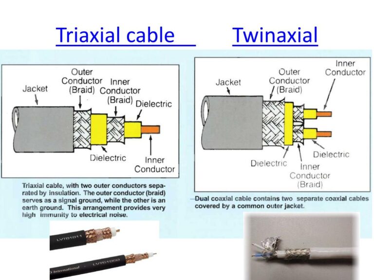
Shielding Systems: Multiple protective layers working together:
- Aluminum foil (100% coverage against RF interference)
- Copper or aluminum braid (typically 60-95% coverage)
- Quad-shield construction (dual foil + dual braid) for maximum EMI rejection
Outer Jacket: Critical for environmental protection:
- UV-stabilized polyethylene (PE) for direct sunlight exposure
- Polyvinyl chloride (PVC) for moderate outdoor applications
- Linear low-density polyethylene (LLDPE) for extreme temperature ranges
Technical Specifications Comparison
| Parameter | RG6 Quad-Shield | RG11 Tri-Shield | Standards Compliance |
|---|---|---|---|
| Impedance | 75Ω ±3Ω | 75Ω ±3Ω | IEC 61196-1 |
| Velocity of Propagation | 0.85 | 0.82 | ASTM D4566 |
| Center Conductor | 18 AWG (1.02mm) | 14 AWG (1.63mm) | MIL-C-17 |
| Attenuation @ 1GHz | 6.8 dB/100ft | 4.5 dB/100ft | SCTE 74 |
| Shield Effectiveness | >110dB | >90dB | IEC 62153-4-4 |
| UV Resistance | 5+ years | 5+ years | UL 2556 |
| Minimum Bend Radius | 2.5″ (63.5mm) | 4.5″ (114.3mm) | TIA/EIA-568 |
| Operating Temp Range | -40°C to +80°C | -40°C to +80°C | MIL-STD-810G |
Environmental Challenges and Protection Strategies
UV Radiation Effects and Mitigation
Ultraviolet radiation represents one of the most persistent threats to outdoor cable installations. UV exposure causes:
- Jacket material degradation through polymer chain breaking
- Increased brittleness and reduced flexibility
- Color fading indicating compromised outer protection
- Eventual cracking leading to moisture ingress
Protection Strategies:
- Select cables with carbon black UV inhibitors (minimum 2.5% concentration)
- Install in UV-resistant conduit for maximum protection
- Utilize cable trays with protective covers in high-exposure areas
- Apply UV-protective wrapping for retrofit applications
Moisture Ingress Prevention
Water infiltration remains the primary cause of signal degradation and failure in outdoor coaxial systems. Once moisture enters the cable structure, it can:
- Alter the dielectric properties, changing the cable’s impedance
- Create corrosion at connection points
- Cause short circuits in power-carrying applications
- Lead to complete signal loss during freezing conditions
According to search results, proper weatherproofing can prevent these issues through multiple protection layers.
Temperature Fluctuation Management
Daily and seasonal temperature variations cause expansion and contraction cycles that stress cable components:
- Jacketing expansion coefficients: 9.5-15 × 10^-5 cm/cm/°C
- Metallic components: 1.7-2.3 × 10^-5 cm/cm/°C
This differential can lead to separation between layers and eventual performance degradation.
Engineering Solutions:
- Leave appropriate slack (service loops) to accommodate thermal expansion
- Install specialized expansion fittings at building entry points
- Use temperature-stabilized cable formulations with matched expansion coefficients
Cable Selection Methodology for Outdoor Applications
Application-Specific Selection Criteria
Different outdoor environments require specific cable characteristics:
Direct Burial Applications:
- Flooded cable construction with water-blocking gel
- Robust PE jacket (minimum 3mm thickness)
- Double or triple shielding for ground interference rejection
- Crush resistance exceeding 1000N/100mm
Aerial Installations:
- Self-supporting messenger wire integration
- Enhanced UV protection (minimum 5-year rating)
- Wind and ice-load calculations per local building codes
- Temperature rating matching regional extremes
Building Exterior Mounting:
- Fire rating compliance (CMX, CATVX or equivalent)
- Physical protection against wildlife damage
- Appearance considerations (black vs. white jackets for heat absorption)
Distance-Based Selection Parameters
Signal attenuation increases with distance, requiring careful cable selection based on run length:
- For runs under 150 ft (45m): Standard RG6 provides adequate performance
- For runs between 150-500 ft (45-150m): RG11 delivers superior signal integrity
- For runs exceeding 500 ft (150m): Consider signal amplification or alternative technologies
When comparing RG6 versus RG11 for long-distance applications, RG11 offers approximately 30-35% less attenuation at equivalent frequencies due to its larger center conductor and dielectric dimensions.
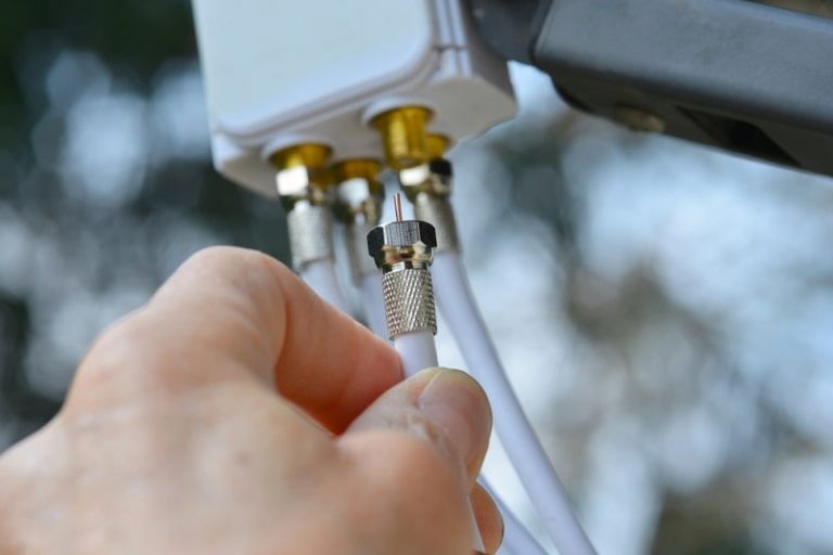
Professional Weatherproofing Techniques
Connection Point Protection Systems
The connection interface between cable and connector represents the most vulnerable point for moisture ingress. Multiple weatherproofing approaches exist with varying effectiveness:
Self-Amalgamating Tape Method:
- Clean connector and cable thoroughly with isopropyl alcohol
- Apply silicone dielectric grease to connector threads
- Wrap connection with self-amalgamating tape, extending 1″ (25mm) beyond connector on each side
- Overlap tape by 50% minimum during application
- Finish with UV-resistant electrical tape outer layer
Heat-Shrink Tubing Application:
- Select adhesive-lined, UV-stabilized heat-shrink tubing sized for your connection
- Position tubing to cover entire connector and extend onto cable jacket
- Apply heat evenly using heat gun (350-400°F/175-200°C)
- Ensure adhesive flows at ends to create complete seal
- Allow to cool before handling or stressing connection
Specialized Cold-Shrink Systems:
- Select silicone (not EPDM) cold-shrink tubing for coaxial applications
- Ensure proper sizing for cable/connector combination (see manufacturer specifications)
- Position tubing with core removed to create IP68-rated seal
- Verify that shrink material contracts to form tight seal on both connector and cable
Research indicates that silicone cold-shrink systems provide superior weatherproofing compared to other methods, consistently achieving IP68 ratings in laboratory testing.
Weatherproofing Verification Protocols
After applying weatherproofing solutions, verification testing ensures effectiveness:
- Visual inspection: Check for complete coverage and proper adhesion
- Water resistance test: Apply gentle water spray at various angles to verify seal integrity
- Physical stress test: Apply gentle flexing force to ensure weatherproofing remains intact
- Documentation: Photograph completed connections for installation records
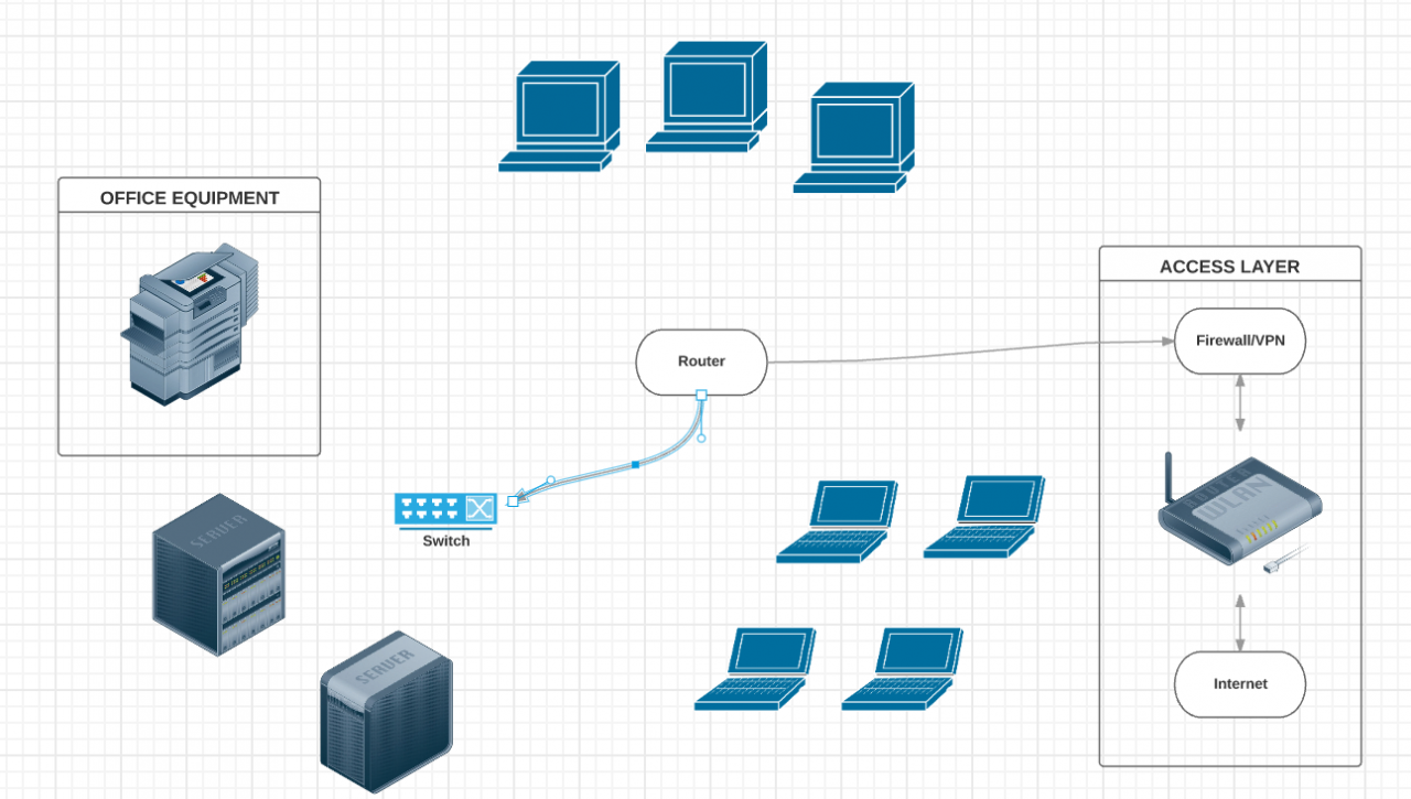
Installation Best Practices for Maximum Durability
Precision Routing Techniques
Proper cable routing significantly impacts system longevity. Follow these engineering guidelines:
- Maintain minimum bend radius (typically 10× cable diameter)
- Install drip loops before building entry points
- Route along existing structural elements for physical protection
- Avoid high-temperature areas (exhaust vents, HVAC equipment)
- Maintain separation from power cables per NEC requirements
Secure Mounting Methods
Properly securing outdoor coaxial cable prevents damage from wind, ice loading, and thermal expansion:
- Use UV-resistant cable ties with minimum 50lb tensile strength
- Space fasteners at maximum 24″ (60cm) intervals for horizontal runs
- Space fasteners at maximum 36″ (90cm) intervals for vertical runs
- Use cushioned clamps around sharp edges
- Allow 2-3mm of movement within fasteners to permit thermal expansion
Ground Fault Protection and Lightning Mitigation
All outdoor coaxial installations require proper grounding to protect equipment and personnel:
- Install lightning arrestors at building entry points
- Ground coaxial shields to NEC-compliant ground systems
- Implement single-point grounding to avoid ground loops
- Bond all metallic components to common ground
- Consider fiber optic solutions for extreme lightning exposure areas
Connector Selection and Termination Protocols
Weatherproof Connector Options
The connector interface is critical for system performance and durability. Select connectors based on these criteria:
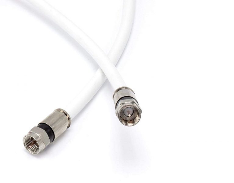
F-Type Connectors:
- Use compression-type connectors with internal O-rings
- Avoid crimp or twist-on types for outdoor applications
- Select brass or nickel-plated brass for corrosion resistance
- Ensure minimum 15lb (6.8kg) pull-out resistance
N-Type Connectors:
- Use connectors with silicone gaskets
- Select stainless steel versions for coastal environments
- Verify minimum IP67 rating for outdoor applications
- Apply recommended torque (typically 12-15 inch-pounds)
Professional Termination Procedure
Follow this detailed process for weatherproof cable termination:
- Preparation:
- Cut cable squarely using professional cable cutter
- Measure and mark proper strip dimensions per connector specifications
- Select calibrated stripping tool for your specific cable type
- Stripping:
- Remove outer jacket without scoring shield
- Fold back braided shield without fraying
- Trim dielectric to expose center conductor
- Verify dimensions match connector requirements
- Connector Application:
- Apply dielectric grease to connector body
- Seat cable fully in connector housing
- Verify center conductor extends proper distance
- Compress using calibrated compression tool
- Weatherproofing:
- Apply weatherproofing immediately after termination
- Document installation with photographs
- Label connection for future maintenance
For detailed step-by-step termination instructions, refer to our comprehensive guide on How To Terminate The Coaxial Cable.
Troubleshooting and Maintenance Protocols
Signal Quality Assessment
Regular signal testing helps identify potential issues before complete failure:
- Signal Level Testing:
- Measure signal strength at installation (baseline)
- Retest quarterly using calibrated signal level meter
- Document readings for trend analysis
- Return Loss Measurement:
- Minimum 20dB return loss indicates good connection
- Values below 15dB suggest connector issues
- Document changes exceeding 3dB for investigation
- Visual Inspection Schedule:
- Monthly inspection of exposed connections
- Quarterly inspection of all accessible components
- Annual comprehensive system evaluation
Common Failure Points and Remediation
| Failure Point | Diagnostic Indications | Remediation Strategy |
|---|---|---|
| Connector corrosion | Intermittent signal, increasing noise | Replace connector and improve weatherproofing |
| Water migration | Signal degradation during/after rain | Identify entry point, replace affected section |
| UV damage | Visible jacket cracking or discoloration | Replace damaged sections, improve protection |
| Physical damage | Visible kinks, crushing, or animal damage | Replace damaged sections, add mechanical protection |
| Ground potential issues | Intermittent picture or data errors | Verify single-point grounding, check for loops |
Regulatory Compliance and Industry Standards
2025 Code Requirements
Current regulations affecting outdoor coaxial installations include:
- National Electrical Code (NEC) Article 820: Communications circuits requirements
- TIA/EIA-568.4: Commercial building telecommunications cabling standard
- Construction Products Regulation (CPR): Fire performance requirements
- UL Standards: Safety certification requirements
When installing outdoor coaxial systems, ensure compliance with local building codes and jurisdictional requirements that may exceed national standards.
Environmental Compliance
Modern cable installations must address environmental concerns:
- RoHS compliance for restriction of hazardous substances
- REACH registration for chemical components
- End-of-life recycling considerations per local regulations
- Wildlife protection requirements (bird-friendly designs)
Conclusion: Ensuring Long-Term Outdoor Coaxial Performance
Creating weatherproof, durable outdoor coaxial installations requires attention to multiple engineering factors. By selecting appropriate cable types, implementing professional weatherproofing techniques, following precise installation protocols, and establishing regular maintenance schedules, you can create systems that deliver reliable performance across decades of service.
Key takeaways from this engineering guide include:
- Select cable construction specifically rated for your environmental conditions
- Implement multi-layer weatherproofing at all connection points
- Follow proper installation techniques that account for environmental stresses
- Document your installation for future reference and maintenance
- Establish regular inspection and testing protocols
For more information on related topics, explore our articles on RG11 Coaxial Cable, What Is Coaxial Cable, and Advanced CCTV Network Design Strategies.