In telecommunications and networking infrastructure, coaxial cable connectors serve as critical components that maintain signal integrity across various applications. With the recent updates to IEC 61196-1-112:2025 standards focusing on improved testing methods for return loss and Voltage Standing Wave Ratio (VSWR), understanding the distinct characteristics and applications of different connector types has become increasingly important for both professional installers and technology enthusiasts.
This comprehensive guide explores the four most common coaxial connector types-F-Type, BNC, SMA, and N-Type-detailing their technical specifications, optimal applications, installation best practices, and troubleshooting techniques based on current industry standards and practices.
Understanding Coaxial Cable Fundamentals
Before diving into specific connector types, it’s essential to understand the basic structure and function of coaxial cables that necessitate these specialized connectors.
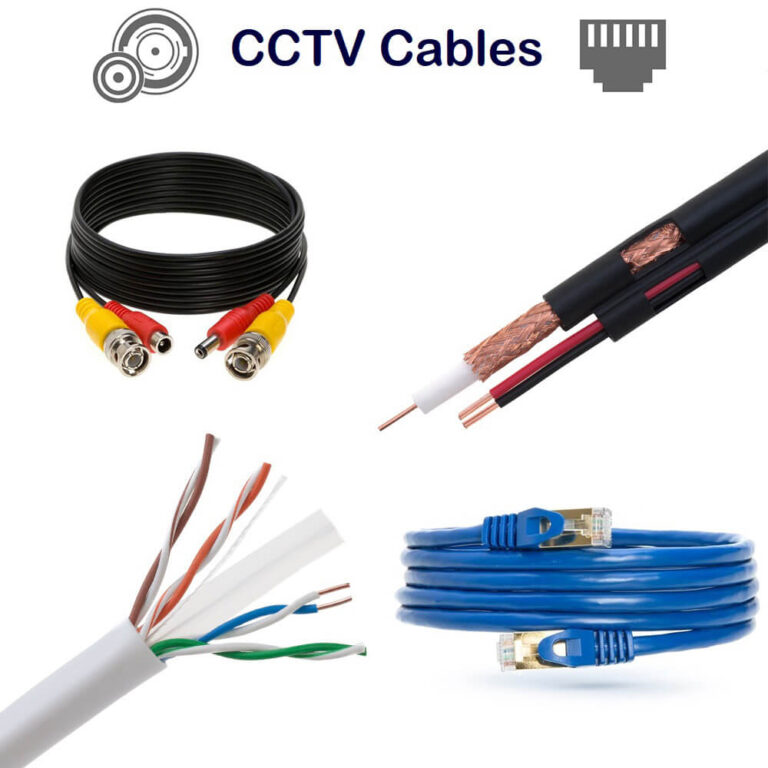
Coaxial Cable Construction
Coaxial cables feature a layered design that provides superior signal protection:
- Center conductor: Typically copper or copper-clad steel that carries the signal
- Dielectric insulator: Surrounds the center conductor, providing electrical isolation
- Metallic shield: Braided or foil shield (sometimes both) that blocks external interference
- Outer jacket: Protective covering that shields against environmental factors
This concentric design allows coaxial cables to carry high-frequency signals with minimal interference and signal loss, making them ideal for applications ranging from residential cable television to high-performance telecommunications infrastructure.
Impedance Considerations
One of the most critical specifications when selecting coaxial connectors is impedance matching. The two standard impedance values in coaxial systems are:
- 50 ohms: Primarily used in data transmission, test equipment, and RF applications
- 75 ohms: Commonly used in video applications, cable television, and satellite systems
Using connectors with mismatched impedance can result in signal reflection, standing waves, and significant power loss.
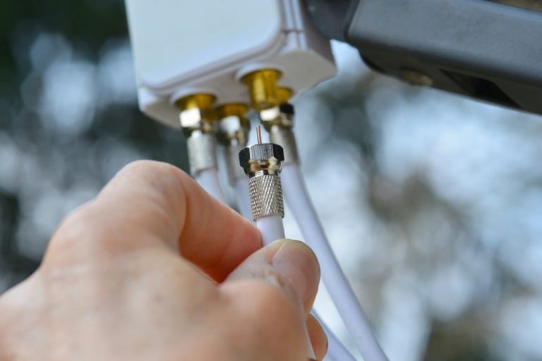
F-Type Connectors
F-Type connectors represent the most common connector type found in residential installations, primarily for television and internet service.
Technical Specifications
| Parameter | Specification |
|---|---|
| Impedance | 75 ohms |
| Frequency Range | DC to 1 GHz (standard)DC to 3 GHz (high-performance) |
| Thread Size | 3/8-32 thread |
| Typical Applications | Cable TV, satellite systems, DOCSIS internet |
| Connection Method | Threaded |
Design Features
F-Type connectors feature a unique design where the center conductor of the coaxial cable itself serves as the connector’s center pin. This simplifies the connector structure but requires precise cable preparation to ensure proper electrical contact and mechanical stability.
The standard F-Type connector uses a threaded coupling mechanism with a 3/8-32 thread specification. This thread pitch provides a secure connection that resists vibration while allowing for relatively easy installation and removal.
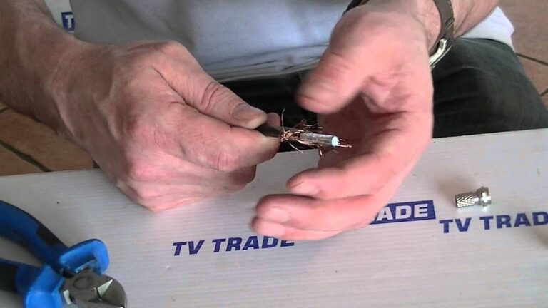
Installation Methods
When installing F-Type connectors, precision in cable preparation is crucial. Follow these steps for optimal results:
- Cut the cable squarely using a proper cable cutter
- Strip the outer jacket, shield, and dielectric using a properly calibrated coaxial stripper tool
- Prepare the connector based on its specific type:
- Compression connectors: Slide the connector onto the prepared cable and use a compression tool to secure it
- Crimp connectors: Position the connector and use a hex crimping tool to secure it
- Twist-on connectors: Thread the connector onto the prepared cable with a clockwise motion
For more detailed guidance, refer to our complete guide on terminating coaxial cables.
Common Applications
F-Type connectors are predominantly used in:
- Residential cable television distribution
- Satellite receiver connections
- Cable modem installations for internet service
- Over-the-air antenna connections to televisions
Their widespread adoption in consumer applications stems from their relatively low cost, adequate performance for residential frequency ranges, and ease of installation.
BNC Connectors
BNC (Bayonet Neill-Concelman) connectors represent a versatile connector type widely used in professional video, test equipment, and some networking applications.
Technical Specifications
| Parameter | Specification |
|---|---|
| Impedance | 50 or 75 ohms |
| Frequency Range | DC to 4 GHz (standard)DC to 10 GHz (precision versions) |
| Connection Type | Bayonet (twist-lock) |
| Typical Applications | Test equipment, broadcast video, security cameras |
| Durability | >500 mating cycles per IEEE 287.1 |
Design Features
The distinguishing feature of BNC connectors is their bayonet coupling mechanism, which allows for quick connection and disconnection with a quarter-turn. This design makes them ideal for applications requiring frequent reconfiguration of equipment.
BNC connectors are available in both 50-ohm and 75-ohm impedance versions, making them suitable for both RF/data applications and video systems. It’s crucial to use the correct impedance version for your specific application to avoid signal degradation.
Installation Methods
Installing BNC connectors requires attention to detail:
- Cut the cable precisely at 90 degrees
- Use a cable stripper to expose the correct lengths of center conductor, shield, and dielectric
- For crimp-style connectors:
- Slide the crimp sleeve onto the cable
- Insert the cable into the connector body until the dielectric is flush with the center pin
- Crimp the connector using a properly calibrated crimping tool
- For solder-style connectors:
- Prepare the cable as above
- Solder the center conductor to the center pin
- Crimp or solder the shield connection
Common Applications
BNC connectors are commonly used in:
- Professional video equipment (75-ohm versions)
- Test and measurement equipment (50-ohm versions)
- Security camera systems
- Legacy Ethernet networks (10BASE-2)
- Laboratory instrumentation
The quick-connect nature and reliable performance of BNC connectors have made them a standard in professional environments where equipment may need to be reconfigured frequently.
SMA Connectors
SMA (SubMiniature version A) connectors are precision RF connectors designed for higher frequency applications in a compact form factor.
Technical Specifications
| Parameter | Specification |
|---|---|
| Impedance | 50 ohms (typical) |
| Frequency Range | DC to 18 GHz (standard)DC to 26.5 GHz (precision) |
| Thread Size | 1/4-36 UNS |
| Torque Specification | 0.9-1.1 N·m per IEEE 287.3 |
| Typical Applications | Wireless communications, test equipment, RF modules |
Design Features
SMA connectors feature a threaded coupling mechanism with a hex nut for secure attachment. Their compact size makes them ideal for dense electronic equipment where space is limited.
The center conductor is supported by a PTFE (Teflon) dielectric, providing excellent electrical characteristics at high frequencies. According to the latest IEEE 287.1-2021 standards, these connectors maintain consistent performance across their rated frequency range when properly installed.
Installation Methods
Installing SMA connectors requires precision tools and careful technique:
- Cut and strip the cable according to the connector manufacturer’s specifications
- For crimp-style SMA connectors:
- Slide the crimp sleeve onto the cable
- Insert the cable into the connector body
- Crimp the center pin to the center conductor
- Crimp the outer sleeve to secure the shield
- For solder-style SMA connectors:
- Solder the center conductor to the center pin
- Solder the shield to the connector body
- Use a calibrated torque wrench to tighten SMA connections to 0.9-1.1 N·m
Important: Over-tightening SMA connectors is a common mistake that can damage the connector and impair performance. Always use a torque wrench for final tightening.
Common Applications
SMA connectors are widely used in:
- Wireless communication systems
- RF test equipment
- Wi-Fi antenna connections
- Cellular equipment
- Microwave components
- Precision test and measurement setups
Their excellent performance at high frequencies and compact size make them ideal for modern wireless and telecommunications equipment.
N-Type Connectors
N-Type connectors represent a robust, weatherproof solution for applications requiring reliability in demanding environments.
Technical Specifications
| Parameter | Specification |
|---|---|
| Impedance | 50 ohms (standard)75 ohms (specialized) |
| Frequency Range | DC to 11 GHz (standard)DC to 18 GHz (precision) |
| Thread Size | 5/8-24 UNEF |
| Torque Specification | 2.3-2.8 N·m per MIL-STD-348 |
| Power Handling | Up to 2,500W @ 1 GHz |
| Weather Resistance | IP67 rated for outdoor applications |
Design Features
N-Type connectors (named after inventor Paul Neill) feature a robust physical design with excellent weather resistance, making them ideal for outdoor and industrial applications.
Their threaded coupling mechanism provides a secure connection, while internal gaskets in weatherproof versions prevent moisture ingress. The larger physical size compared to other RF connectors facilitates higher power handling capabilities, making them suitable for transmitter applications.
Installation Methods
Installing N-Type connectors follows these general steps:
- Cut the cable squarely using appropriate cable cutters
- Strip the cable according to the specific connector dimensions using a precise stripping tool
- For crimp-style N-Type connectors:
- Slide the crimp sleeve onto the cable
- Insert the cable into the connector body
- Crimp the center pin to the center conductor
- Crimp the outer sleeve to secure the shield
- For solder-style N-Type connectors:
- Solder the center conductor to the center pin
- Solder the shield connection as specified by the manufacturer
- For outdoor installations, apply dielectric grease and weatherproofing materials according to manufacturer specifications
Common Applications
N-Type connectors are predominantly used in:
- Wireless base station equipment
- Broadcast transmitters
- High-power RF systems
- Outdoor antenna installations
- Industrial RF applications
- Military and aerospace systems
Their robust construction and excellent weatherproofing make them the preferred choice for critical infrastructure and outdoor installations.
Connector Selection Guide
Selecting the appropriate connector type depends on several factors including frequency range, power requirements, environmental conditions, and application needs.
Selection Factors
Consider these key factors when selecting a coaxial connector:
- Frequency range: Higher frequencies require connectors designed for minimal signal loss at those frequencies
- Impedance: Must match the system impedance (typically 50 or 75 ohms)
- Power handling: Higher power applications require connectors with robust construction
- Environmental exposure: Outdoor installations require weatherproof connectors
- Connection frequency: How often the connection will be made/broken
- Physical space constraints: Some applications require compact connectors
- Budget considerations: Cost per connection point versus performance requirements
Application-Specific Recommendations
| Application | Recommended Connector | Rationale |
|---|---|---|
| Home Cable TV | F-Type | Cost-effective, standard for 75Ω systems |
| Security Cameras | BNC | Quick-connect, industry standard for video |
| Wi-Fi Antenna | SMA or RP-SMA | Compact size, good performance to 6 GHz |
| Outdoor Base Station | N-Type | Weather resistant, high power handling |
| Test Equipment | BNC or SMA | Dependent on frequency range requirements |
| Broadcast Video | BNC (75Ω) | Industry standard for professional video |
| Military/Aerospace | TNC or N-Type | Vibration resistance, reliability |
For further guidance on coaxial cable selection for specific applications, see our article on choosing the right coaxial cable for HDTV antennas.
Installation Best Practices
Regardless of connector type, following proper installation practices is essential for optimal signal performance and system reliability.
Tools and Preparation
A professional installation requires the right tools:
- Cable cutters: For clean, square cuts
- Coaxial stripping tool: Calibrated for the specific cable type
- Crimping/compression tools: Matched to the specific connector type
- Torque wrench: For threaded connectors requiring precise tightening
- Signal tester: To verify installation quality
Quality tools represent a worthwhile investment for consistent, reliable installations. For detailed information on specialized tools, refer to our guide on cable stripping and cutting tools.
Common Installation Mistakes
Avoid these frequent installation errors:
- Improper cable preparation: Incorrect stripping dimensions leading to shorts or poor connections
- Over-tightening threaded connectors: Especially critical with SMA connectors
- Using incorrect impedance connectors: Mixing 50Ω and 75Ω components
- Incorrect crimping: Using improper tools or insufficient compression force
- Excessive cable bending: Creating strain or potential damage near connectors
- Ignoring weather protection: Failing to weatherproof outdoor connections
- Using low-quality connectors: Saving money upfront but causing reliability issues
Signal Testing and Verification
After installation, verification is crucial:
- Visual inspection: Check for proper seating, exposed shields, and center conductor position
- Continuity testing: Verify electrical continuity through the connection
- Signal quality testing: Measure signal strength, noise, and interference levels
- Return loss/VSWR testing: For critical installations, measure signal reflections
- Long-term monitoring: Document baseline performance for future comparison
For complex installations, consider using a Vector Network Analyzer (VNA) or Time Domain Reflectometer (TDR) to verify connection quality according to the latest IEC 61196-1-112:2025 standard requirements.
Troubleshooting Common Issues
Even with careful installation, connector issues can arise. Here’s how to diagnose and resolve common problems.
Signal Loss and Interference
If experiencing signal degradation:
- Check connector tightness: Ensure threaded connectors are properly tightened
- Inspect for physical damage: Look for bent pins, crushed connectors, or damaged cables
- Test for shorts or opens: Use a multimeter to check for electrical problems
- Replace weatherproofing: For outdoor installations, check for moisture ingress
- Verify proper grounding: Ensure the shield is properly grounded throughout the system
Physical Connection Issues
For mechanical connection problems:
- Cross-threading: Replace connectors if threads are damaged
- Corrosion: Clean contacts with appropriate contact cleaner or replace connectors
- Mechanical strain: Add strain relief or reroute cables to reduce physical stress
- Vibration loosening: Apply appropriate thread-locking methods for high-vibration environments
- Cold solder joints: Resolder connections that appear dull or grainy
Testing Equipment and Methods
Professional testing can identify subtle issues:
- Signal level meters: Measure actual signal strength at various points
- Spectrum analyzers: Identify interference sources and signal quality issues
- Time Domain Reflectometers: Locate impedance mismatches and cable faults
- Network analyzers: Measure advanced parameters like return loss and insertion loss
For information on cable signal testing, see our step-by-step guide on mastering cable signal testing.
Industry Trends and Future Developments
The coaxial connector market continues to evolve with new applications and technologies.
Market Growth and Development
According to recent industry analysis, the RF coaxial connector market is projected to grow significantly, with a compound annual growth rate (CAGR) of 9.0% from 2025 to 2030. This growth is driven by expanding applications in 5G infrastructure, IoT devices, and advanced military/aerospace systems.
Key trends include:
- Miniaturization: Development of smaller connectors for compact devices
- Higher frequency capabilities: Connectors now operating above 145 GHz
- Improved materials: Enhanced performance through advanced metallurgy and dielectrics
- Integrated solutions: Connectors combined with other components for space efficiency
- Environmental considerations: Reduction in harmful materials and improved sustainability
Emerging Standards and Technologies
Current technical developments focus on:
- Updated testing methods: The IEC 61196-1-112:2025 standard now emphasizes improved testing for return loss and VSWR, especially for applications above 1.8 GHz
- Higher frequency applications: Development of connectors for millimeter-wave and terahertz frequencies
- Enhanced weatherproofing: New sealing technologies for harsh environment applications
- Simplified installation: Tool-less designs that maintain performance while reducing installation complexity
- Smart connectors: Integration of monitoring capabilities to report connection quality and predict failures
For professionals looking to stay current with these developments, the IEEE-287-2021 standard provides updated test methods and specifications for RF connectors across various applications.
Conclusion
Coaxial connectors play a critical role in maintaining signal integrity across the telecommunications and networking landscape. Understanding the distinct characteristics and appropriate applications for F-Type, BNC, SMA, and N-Type connectors enables network professionals and technology enthusiasts to make informed decisions for their specific requirements.
As we’ve explored, each connector type offers unique advantages in terms of frequency range, power handling, environmental durability, and ease of installation. By following proper selection criteria, installation best practices, and maintenance procedures, you can ensure optimal performance and longevity for your coaxial cable infrastructure.
With the continuing advancement of wireless and networking technologies, staying informed about connector standards and specifications remains essential for anyone working with RF systems. The significant market growth projected through 2030 highlights the enduring importance of these seemingly simple but technically sophisticated components.
For additional information on related topics, explore our comprehensive guides on coaxial cable types and specifications and mastering coaxial cable impedance.