In the realm of network infrastructure, coaxial cable impedance represents a critical specification that significantly impacts system performance, signal integrity, and overall reliability. For network engineers, the choice between 50Ω and 75Ω coaxial systems involves far more than simple numerical differences-it requires a deep understanding of electromagnetic principles, signal behavior, and application-specific requirements.
This comprehensive technical guide examines the core differences between 50Ω and 75Ω coaxial systems according to the latest 2025 industry standards, providing network engineers with actionable insights for optimal system design and implementation.
The Physics of Coaxial Cable Impedance
Coaxial cable impedance is defined by the cable’s physical construction and represents the resistance to alternating current flow. Unlike simple DC resistance, impedance is a complex value measured in ohms (Ω) that encompasses both resistive and reactive components.
The characteristic impedance (Z₀) of a coaxial cable is determined by the following formula:
Z₀ = (138 × log₁₀(D/d))/√εᵣ
Where:
- D = inner diameter of outer conductor
- d = outer diameter of inner conductor
- εᵣ = relative permittivity (dielectric constant) of insulating material
This formula demonstrates why impedance cannot be altered without changing the cable’s physical dimensions or materials-it’s inherent to the cable’s construction.
50Ω Coaxial Systems: Technical Specifications and Applications
Core Technical Characteristics
50Ω coaxial cables are engineered primarily for RF transmission applications where power handling capabilities are prioritized. According to specifications from the latest ANSI/TIA-568.4-E standard (2023 update), these cables feature:
- Center Conductor: Typically larger diameter (compared to 75Ω) for improved power handling
- Dielectric Material: Often PTFE (Teflon) or polyethylene with precisely calculated dimensions
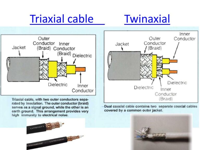
- Shielding: Multiple layers including braided copper and aluminum foil
- Velocity Factor: Typically 0.66-0.82 depending on dielectric material
- Maximum Frequency: Up to 10GHz with standard connectors (higher with specialty types)
Connector Standards
50Ω coaxial systems utilize specific connector types designed to maintain impedance consistency throughout the connection. According to Hirose Electric’s 2025 technical documentation, these include:
- N-Type Connectors: Medium-sized connectors supporting frequencies up to 10GHz, compliant with MIL-C-39012, IEC 60169-16, and JIS C 5411 standards
- BNC Connectors: For lower power applications with quick bayonet coupling
- SMA Connectors: Precision connectors for microwave applications
- TNC Connectors: Threaded version of BNC suitable for high-vibration environments
Primary Applications
50Ω coaxial systems excel in these applications:
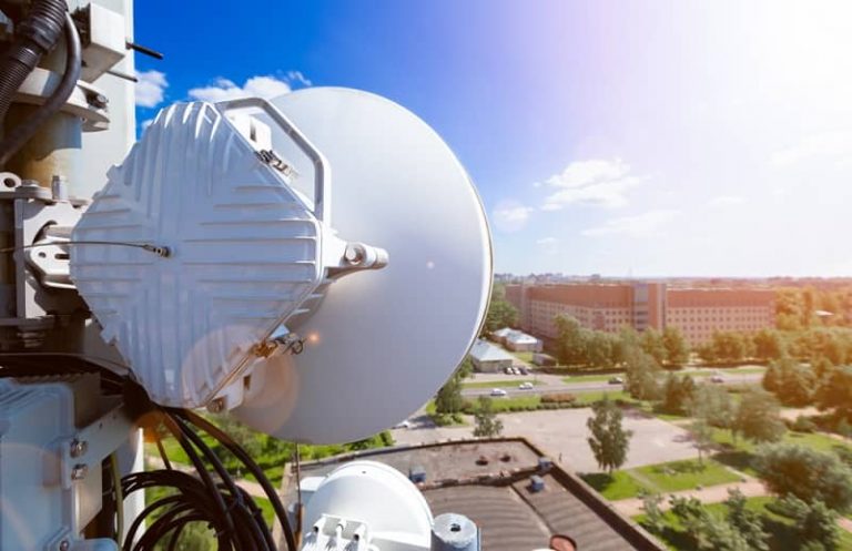
- Wireless communications infrastructure (cellular, Wi-Fi, microwave)
- Test and measurement equipment (network analyzers, signal generators)
- RF transmitters and broadcast equipment
- Military and aerospace communication systems
- Amateur radio installations
75Ω Coaxial Systems: Technical Specifications and Applications
Core Technical Characteristics
75Ω coaxial cables are optimized for signal reception and long-distance transmission with minimal loss. The 2025 ANSI/TIA-568.4-E standard specifies these characteristics:
- Center Conductor: Smaller diameter compared to 50Ω cables, often copper-clad steel
- Dielectric Material: Primarily foam polyethylene for lower signal attenuation
- Shielding: Multiple configurations available (quad-shield, tri-shield, dual-shield)
- Velocity Factor: Typically 0.82-0.88 due to foam dielectric
- Maximum Frequency: Optimized for frequencies up to 3GHz
Common Cable Types
75Ω coaxial infrastructure typically employs these standardized cable types:
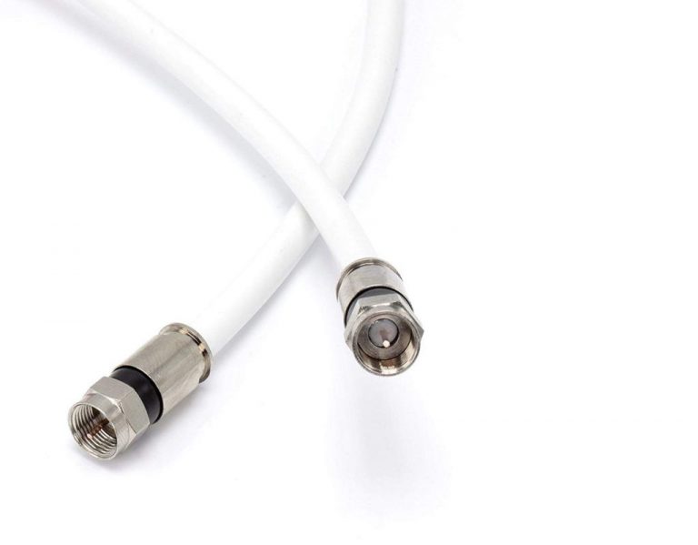
- RG-6: Standard for modern video distribution with quad shielding options
- RG-11: For longer runs, featuring lower attenuation characteristics as detailed in the RG11 Coaxial Cable Guide
- RG-59: Legacy cable for shorter runs in video applications
Primary Applications
75Ω coaxial systems are predominantly used in:
- Cable television (CATV) distribution networks
- Satellite television receiving systems
- Broadband internet connections via cable modems
- Video distribution in commercial and residential buildings
- Security camera systems (CCTV)
Performance Comparison: 50Ω vs 75Ω Systems
The following table compares key performance parameters between 50Ω and 75Ω coaxial systems based on 2025 industry testing standards:
| Performance Parameter | 50Ω Systems | 75Ω Systems | Key Consideration |
|---|---|---|---|
| Signal Attenuation | Moderate | Lower (especially at higher frequencies) | 75Ω superior for long-distance signal transmission |
| Power Handling | Superior (up to 4kW for large cables) | Moderate (not primary design focus) | 50Ω critical for transmitting applications |
| Voltage Standing Wave Ratio (VSWR) | 1.2 Max. up to 2GHz (per Hirose specs) | 1.5 Max. up to 3GHz (per TIA-570-D) | Lower VSWR indicates better impedance matching |
| Frequency Range | 0-10GHz (standard), higher for specialty cables | 0-3GHz (optimal range) | Application frequency requirements dictate choice |
| Connector Quality | Precision machined, higher cost | Consumer-oriented, lower cost | System reliability vs. budget considerations |
Impedance Matching: Critical for System Performance
Impedance matching represents perhaps the most crucial aspect of coaxial system design, directly impacting signal integrity and power transfer efficiency.
Effects of Impedance Mismatch
When impedances are mismatched:
- Signal Reflection: Energy bounces back toward the source, creating standing waves
- Power Loss: Reduced power transfer efficiency (quantified by return loss)
- Signal Distortion: Especially problematic for digital signals at higher frequencies
- Equipment Stress: Possible damage to transmitters or other sensitive components
The degree of impedance mismatch is quantified by Voltage Standing Wave Ratio (VSWR):
VSWR = (1 + |Γ|)/(1 – |Γ|)
Where Γ (reflection coefficient) = (Z₁ – Z₀)/(Z₁ + Z₀)
Time Domain Reflectometry (TDR) Testing
Modern network engineers utilize TDR testing to identify impedance mismatches along cable runs. This technique:
- Sends a pulse down the cable
- Measures reflections that occur at impedance discontinuities
- Calculates distance to faults based on signal velocity
- Quantifies the severity of impedance mismatch
For detailed procedures on cable testing, refer to our Cable Signal Testing Guide.
Installation and Termination Best Practices
Proper installation techniques are essential for maintaining the designed impedance characteristics throughout a coaxial system.
Critical Installation Guidelines
- Observe Minimum Bend Radius
- For 50Ω cables: Typically 10× cable outer diameter
- For 75Ω cables: Typically 8× cable outer diameter
- Tighter bends alter impedance characteristics
- Connector Installation Procedure
- Strip outer jacket precisely using calibrated stripping tools
- Avoid nicking or damaging shield layers
- Maintain proper dielectric setback per connector specifications
- Use proper crimping tools calibrated for specific connectors
- Verify connection quality with appropriate testing equipment
For detailed step-by-step instructions, see our F-Connector Crimping Guide and Coaxial Cable Connection Guide.
Cable Support and Environmental Considerations
- Maximum Pulling Tension: Never exceed manufacturer specifications
- Support Intervals: Typically 3-4 feet horizontal, 5-6 feet vertical
- Temperature Ranges: Consider expansion/contraction in extreme environments
- Weather Protection: Use appropriate boots/sealing for outdoor connections
Industry Standards and Compliance
Network installations must adhere to recognized standards for performance, safety, and interoperability.
Key Standards for Coaxial Systems
- ANSI/TIA-568.4-E (2023): The primary U.S. commercial building telecommunications standard for 75Ω broadband coaxial cabling, cables, cords, and connecting hardware
- IEC 60169-16: International standard for RF connectors used with 50Ω coaxial cables
- MIL-DTL-17: Military specification for coaxial cables in defense applications
- SCTE Standards: Society of Cable Telecommunications Engineers standards for CATV applications
The ANSI/TIA-568.4-E standard “establishes performance and technical criteria for coaxial cabling system configurations for accessing and connecting their respective elements,” as stated by the Telecommunications Industry Association.
Choosing Between 50Ω and 75Ω Systems
The decision between 50Ω and 75Ω coaxial systems should be guided by specific application requirements rather than personal preference.
Decision Matrix for Network Engineers
| Application Need | Recommended System | Justification |
|---|---|---|
| RF Transmission | 50Ω | Optimized for power transfer efficiency |
| Long-Distance Signal Distribution | 75Ω | Lower attenuation characteristics |
| Test & Measurement Equipment | 50Ω | Industry standard for precision equipment |
| Video Distribution | 75Ω | Mathematical optimum for voltage transfer |
| Mixed System Integration | Impedance Transformers Required | Must convert between impedances |
Hybrid System Considerations
When building systems that require both 50Ω and 75Ω components:
- Use appropriate impedance transformers at transition points
- Calculate return loss impact for critical applications
- Consider using separate cable paths for different impedance requirements
- Document all transition points for maintenance purposes
Troubleshooting Common Impedance-Related Issues
Network engineers frequently encounter these impedance-related problems:
1. Signal Loss and Attenuation
Symptoms:
- Reduced signal strength
- Increased bit error rates
- Intermittent connectivity
Diagnostic Approach:
- Measure signal levels at source and destination
- Calculate expected loss based on cable specifications and distance
- Compare actual vs. expected values
- Use spectrum analyzer to examine frequency response curve
Solution Steps:
- Replace damaged cable sections
- Verify connector installation quality
- Add amplification if within specification limits
- Consider lower-loss cable alternatives
2. Standing Wave Issues
Symptoms:
- Fluctuating signal levels
- Frequency-dependent performance problems
- Equipment damage in transmitting systems
Diagnostic Approach:
- Measure VSWR using appropriate test equipment
- Identify reflection points using TDR
- Calculate return loss at critical frequencies
Solution Steps:
- Reexamine connector installations
- Add proper termination to unused outputs
- Install attenuators if appropriate
- Replace improperly matched components
For more troubleshooting guidance, see our article on Why Coaxial Cables Fail.
Future Trends in Coaxial Technology
As we progress through 2025, several key trends are shaping the future of coaxial cable technology:
- Higher Frequency Applications: Development of coaxial systems capable of operating efficiently at frequencies above 50GHz for 6G wireless and advanced sensing applications
- Advanced Manufacturing Techniques: Precision extrusion and dielectric forming methods that achieve more consistent impedance characteristics
- Integration with Fiber Systems: Hybrid fiber-coaxial (HFC) systems with improved interfaces and lower insertion loss
- Smart Cable Systems: Embedded monitoring capabilities for predictive maintenance and automatic fault detection
- Sustainable Materials: Eco-friendly jacket and dielectric materials that maintain performance specifications while reducing environmental impact
For more on emerging cable technologies, read our article on Engineering Modern Coaxial Cable.
Conclusion
The choice between 50Ω and 75Ω coaxial systems represents a fundamental engineering decision that impacts every aspect of network performance. Rather than viewing one standard as superior to the other, network engineers should recognize each as optimized for specific applications-50Ω for power transfer and RF transmission, 75Ω for signal reception and long-distance distribution.
By understanding the physical principles that determine impedance characteristics, following industry standards for installation and testing, and selecting the appropriate system for each application, engineers can design reliable, high-performance networks that meet both current requirements and future expansion needs.
As communication technologies continue to evolve, the fundamental principles of coaxial impedance remain constant, making this knowledge an essential component of the network engineer’s toolkit.